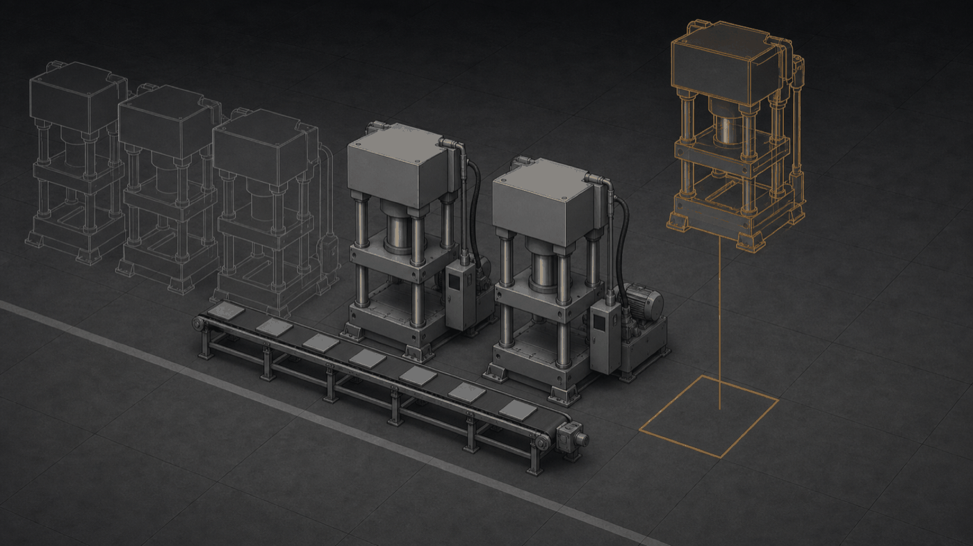
FIG — Equipment is taken from a catalogue and set into an empty placeDashed = not placed yet
Equipment is registered as a component carrying 3D geometry, behaviour parameters and connection rules. Snap them together and the factory stands. When assembly ends, the model is ready to run in Vision Sim.
Layout studies are tied to outside vendors and hand-drawn sheets. When one change costs days, you look at fewer alternatives.
| # | Capability | What it does |
|---|---|---|
| 01 | Component library | Equipment is registered as a component with 3D geometry, behaviour parameters and connection rules. The schema is defined as an AAS (IEC 63278) submodel, so a component built once carries through twin, monitoring and control. STAGE 1 |
| 02 | Component authoring | New equipment is registered from CAD and field measurement, starting with the presses, AMRs and conveyors on the reference floor. STAGE 1 |
| 03 | Snap assembly editor | Drag and drop, and connection rules align and link the parts. The finished assembly is already simulation-ready. STAGE 1 |
| 04 | Layout generation | Give it clearance, traffic and utility rules plus an equipment list, and it produces multiple layout options. STAGE 2 |
| 05 | Sim linkage | Generated layouts are compared directly in Vision Sim — assembly to validation in one flow. STAGE 2 |
| 06 | Robot OLP | Kinematic modelling, interference checks and robot program generation. A track of its own, started after stages 1 and 2. STAGE 3 |
Start with Twin and Sim; Build attaches when it is ready.